Configure 3CX to use DIDforSale DIDs

If you have not checked out DIDforSale and have any need for robust and inexpensive inbound DIDs… do so now.

For those of you who have a 3CX PBX install in addition to DIDforSale DIDs and are having trouble configuring 3CX to correctly talk to the DIDforSale SIP Trunk, this blog entry will save you time and frustration.

NOTE: This entry can also be used to configure multiple DIDs for most other SIP Trunk providers.

Prerequisites

  • You have a fully functional install of 3CX version 9
  • You are not behind a firewall -OR- you have all required ports forwarded to support the SIP protocols
  • You have configured your DIDs to point to your external IP address for 3CX
  • Coffee is brewing

Step#1: Setup a new VOIP provider for DIDforSale
This step creates a generic VOID provider for DIDforSale and setups the basic parameters for the provider.

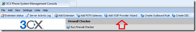
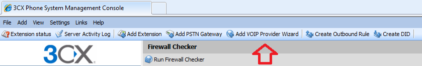
  1. Click the Add VOIP Provider Wizard button located on the toolbar of your 3CX management console
    image
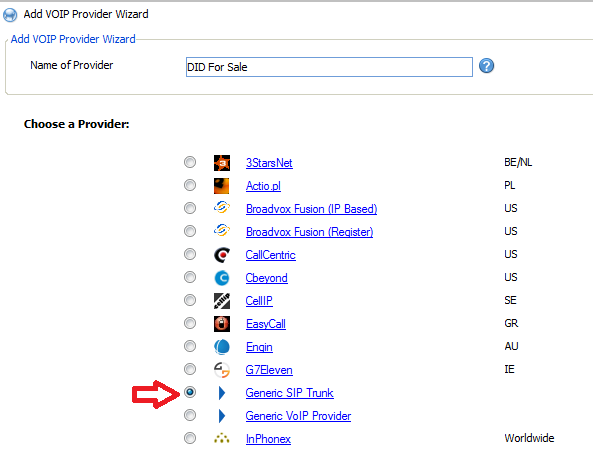
  2. Give the VOIP Provider an appropriate name for your 3CX install and select Generic SIP Trunk
    image
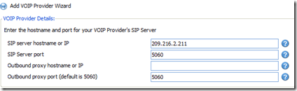
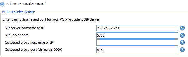
  3. In the VOIP Provider Details screen, enter the SIP server hostname or IP as 209.216.2.211 (the IP for DIDforSale’s SIP server).  Leave all other data as the default
    image
  4. In the Account Details screen, set the value for the fields as follows:
    External Number: Your PIN number as supplied by your Trunk provider
    Authentication ID: Your login account (UserID) as supplied by your Trunk provider
    Authentication Password: Your password as supplied by your Trunk provider
    Maximum simultaneous calls: Whatever your license with 3CX allows
  5. In the Office Hours screen, select any extension you would like this to be forwarded to.�
    NOTE: Anything you set in this screen will be overridden once we setup the inbound DID rules in the next section.
  6. The next screen will attempt to create an outbound call rule for DIDforSale.  Unless you are using DIDforSale as an outbound provider, click the Skip button.

Step#2: Configure the provider’s inbound parameters
This step configures the VOIP provider to properly extract the inbound DID # from the SIP request as sent by DIDforSale.  Without this step, 3CX will not be able to determine which phone number the inbound call is targeted for.

  1. Open and edit the VOIP provider created in Step#1
    image
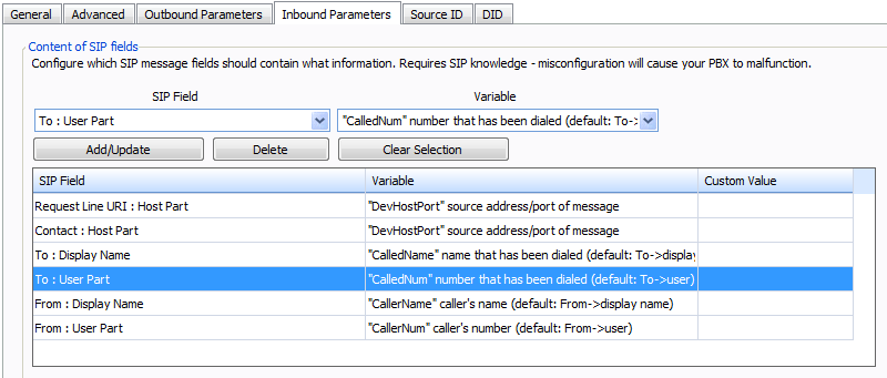
  2. Select the Inbound Parameters tab
  3. Select and delete the To: User Part SIP Field (see highlighted image below)
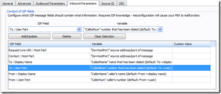
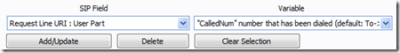
    image
  4. Add a new SIP Field
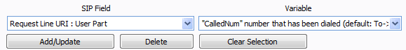
    1st: Set the SIP Field combo box to Request Line URL: User Part
    2nd: Set the variable to “CalledNum” number that has been dialed
    3rd: Click Add/Update
    (See image for selection)
    imageNOTES: DIDforSale sends the destination phone # in the DIDNumber@YourIPAddress format.  This change tells 3CX to pull the CalledNum from the URI (I.E. the inbound phone number is the DIDNumber part of DIDforSale’s inbound request)
  5. Click Apply

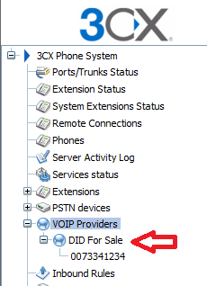
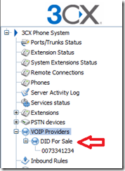
Step#3: Add and route your DID numbers
This step setups each DID number and the internal routing associated with that inbound DID.

  1. Open the VOIP provider created in Step#1
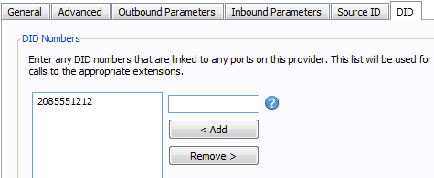
  2. Select the DID tab
  3. Enter your DID number and click Add
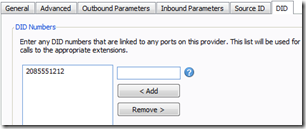
    image
  4. Click Apply
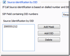
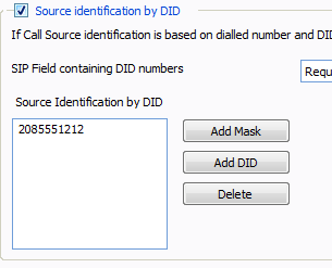
  5. Select the Source ID tab
  6. Make sure the Source identification by DID is checked
  7. Click Add DID and select the DID you added in #3 above
    NOTE: If you do not see the DID number, you forgot to click Apply in #4 above
    image
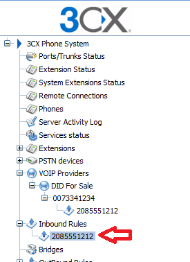
  8. Select the inbound rule which was automatically created when you entered the DID number.
    image
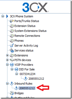
  9. Change the office hours and routing rules to fit your organizations needs for the DID number being configured.
  10. Repeat these steps for each DID number you need to configure

Step#4: Coffee Time!

Creating Hyper-V virtual networks and the dreaded “Cannot bind to” error message

Windows 2008 R2 Hyper-V server is an incredible tool in the IT pro’s test, backup, and recovery arsenal…. as long as everything meshes together nicely.

One of the more interesting errors we see in the field is the dreaded message

Error Applying New Virtual Network Changes
Binding to the external ethernet [NIC goes here] failed.
Cannot bind to [NIC goes here] because it is already bound to another virtual network.

image


We at AIS see this problem most often when dealing with multiple-NIC servers.  The failure scenario goes something like this:

  1. Provision and configure Hyper-V server 2008 R2
  2. Access the new Hyper-V server via Hyper-V Manager on a separate PC
  3. Provision the first NIC under a virtual network
  4. Provision the second NIC under a virtual network (At this point, something goes awry in the Hyper-V Manager due to a variety of RPC / COM issues… the list of which would fill a small book)
  5. The second NIC provisioning is partially active within Hyper-V but is not accessible via the Hyper-V Manager
  6. Any additional attempts to provision the second NIC will now be met with the dreaded “is already bound to another virtual network” error

The quick and dirty solution

  1. Remote desktop into the Hyper-V server
  2. Find the command prompt window
    This is usually located behind the blue colored Server Configuration prompt window
  3. Type the following commands to uninstall and then reinstall the Microsoft Virtual Network Switch Protocols

C:> netcfg –u vms_pp

C:> netcfg –c p –i vms_pp


These two commands will 1st uninstall the virtual switch protocols and then force a reinstall of the same protocols.  This simple two step process forces the invalid virtual network mapping to be cleared from the configuration.

Happy (Virtual) Mappings!

SharePoint Alerts, External Users, and Exchange Relay


One of SharePoint’s nicer features is a rich alert system which supports change driven e-mail based alerts.  Configuring SharePoint and Exchange Server 2007 to e-mail alerts is relatively straight forward for internal e-mail clients (I.E. those e-mail clients which are actually hosted by your Exchange Server).  Configuration becomes much more difficult if you are attempting to alert SharePoint users at e-mail addresses which are NOT hosted on your Exchange Server.  To accomplish this feat, you must relay the e-mail.

This is where the fun begins!

The Scenario
Your e-mail address is internal@yourcompany.com.  Your SharePoint install at http://portal.yourcompany.com is setup to alert you of any changes to your document libraries.  All is well in the world!

A new user is introduced to your SharePoint user list with an e-mail address of external@hotmail.com.  This new user reports he is not receiving any alerts from SharePoint.

A quick review of the logs reveals the following error:

#160009: The e-mail address ‘external@hotmail.com’ is unknown.

Root Problem
Your exchange server is setup to disallow relaying.  Under the hood, SharePoint is receiving the following error from Exchange:

550 5.7.1 Unable to relay

Solution
Enable relaying for your SharePoint server.  Easy huh? Well… sort of.

STEP#1
Open Exchange Management Console and navigate to Server Configuration –> Hub Transport.  Find the Receive Connectors tab.  You should see something similar to the image below:

image

STEP#2
Open the Receive connector and note all of the settings on each screen.  Take good notes as you will need the settings later.
They will look similar to the images below:

imageimageimageimage
SCREEN#1              SCREEN#2              SCREEN#3               SCREEN#4

STEP#3
Remove the receive connector by right clicking on the connector and selecting Remove.
Why do we do this?  Because Exchange Server 2007 appears to process the receive connectors in the order they were created.  In the standard install, the default Receive Connector is configured to receive e-mail from ALL IP addresses.  If you add the Relay Receive Connector AFTER the default connector, it will never be processed.  You want your Relay to process first.

STEP#4
Create the relay connector

  1. Click New Receive Connector on the Action Bar located at the right of the Exchange Management Console.
  2. Name the connector, click Next.
  3. On the Local Network settings screen, modify as necessary.
    NOTE: These will normally be the same as SCREEN#2 in STEP#2 above
    Click Next
  4. On the Remote Network settings screen, remove the default settings by click the red “X”.
  5. Add in the IP address of your internal SharePoint sever.
    NOTE: If your SharePoint server is hosted on the same physical box as the Exchange Server, be sure to enter in the loop back IP address (IPv4 127.0.0.1, IPv6 ::1) as well as the actual IP address of the server.�
    Click Next
  6. Click New to create the Receive Connector, then click FinishBut wait, you are not done just yet!
  7. Right click on the newly created Received Connector and click Properties to edit the Receive Connector
  8. Select the Permission Groups tab
  9. Check the Exchange Server check box
  10. Select the Authentication tab
  11. Check the Externally Secured check box
    Make sure all other check boxes are NOT checked.
  12. Click apply to save your changes

Your new relay connector should look similar to the screenshots below
(Double click to enlarge)

imageimageimageimage
SCREEN#5                  SCREEN#6               SCREEN#7                SCREEN#8

STEP#5
Recreate the original Receive Connector using the settings noted in Step#2
Your receive connector list should now look like the following:

image

STEP#6
Validate functionality

  1. Verify you can still send e-mail.
  2. Verify you can still receive e-mail.
  3. Verify SharePoint is now sending alerts to the external e-mail.
  4. Verify you have no open relays.  This can be completed via any of the available open relay tests on the internet.